
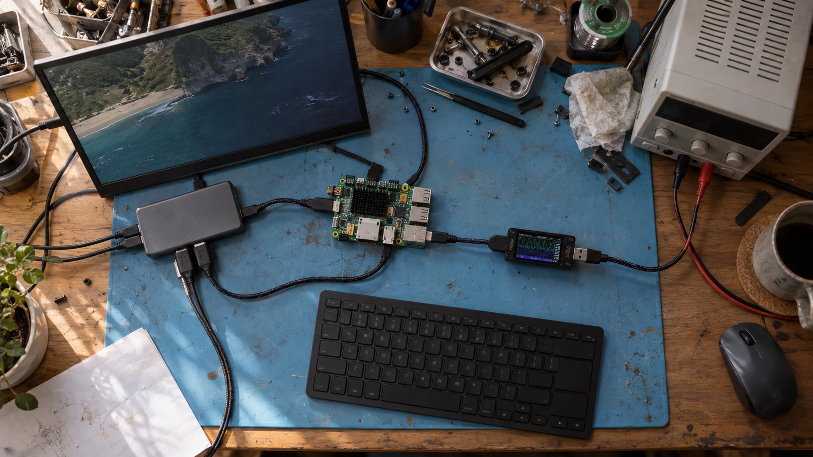
Two USB-C receptacles can look identical while one accepts power only, another provides USB 2.0 device mode, and a third supports USB 3.x host, Power Delivery, and DisplayPort. That visual ambiguity causes requirements to drift: product teams say “add USB-C” while hardware and Android engineers imagine different ports.
Start with a port capability matrix. Define power role, data role, speed, alternate modes, current limits, and behavior for every supported cable orientation and accessory. The connector is the last detail, not the requirement.
Write the port contract before the schematic
USB Type-C separates several roles that older fixed-purpose connectors bundled together. A product may be a power sink, power source, or dual-role power device. Independently, it may be a USB host, USB device, or dual-role data port. DisplayPort Alt Mode adds another negotiation and high-speed routing path.
| Capability question | Example choices | Product decision |
|---|---|---|
| Power role | Sink, source, dual-role | Is the SBC powered through the port, powering accessories, or both? |
| Data role | Host, device, dual-role | Does Android enumerate peripherals or appear as a peripheral? |
| USB speed | USB 2.0, USB 3.x, USB4 where supported | What throughput and routing are required? |
| PD contract | Default Type-C current or negotiated profiles | Which voltages and currents are accepted or supplied? |
| Alternate mode | None or DisplayPort | Must the port drive an external display or dock? |
| Debug/service | ADB, factory tool, recovery, disabled | What is allowed in production? |
Write unsupported cases too. If the product accepts 5 V only and does not implement USB PD, say so. If DisplayPort works only with a full-featured cable and the port cannot provide enough power for a bus-powered dock, document it in the product and test specifications.
Select the Type-C and PD architecture
A simple sink-only USB 2.0 port can use a modest configuration-channel implementation. A dual-role port with PD and DisplayPort normally needs a Type-C/PD controller, orientation switch, high-speed multiplexer, protection, power-path control, and coordinated software.
The CC pins detect attachment, orientation, and advertised current. USB PD messages negotiate higher or different power contracts and discover alternate modes. Do not infer a PD contract from VBUS voltage alone; log the controller state and negotiated result.
High-speed lanes need an orientation switch because the plug can be inserted either way. When DisplayPort is supported, a multiplexer routes lanes between USB and the alternate mode. The Linux Type-C framework can expose ports, partners, cables, roles, and alternate modes, but a vendor BSP still needs correct controller, mux, PHY, and policy drivers.
Freeze the controller firmware with the Android release. A PD firmware update can change negotiation timing or cable compatibility even when the application image is unchanged.
Prevent power-path surprises
For a sink port, define the minimum source that can boot the full product. Include display backlight, USB peripherals, radio peaks, battery charging, and conversion loss. If Android starts before a stable contract is available, inrush or a later load step can collapse VBUS.
For a source port, budget VBUS current per supported contract and protect against short circuit, overcurrent, overvoltage, reverse current, and excessive connector temperature. A product powered from 12 V cannot promise every 20 V PD behavior simply because the controller supports the protocol.
Dual-role power needs a clear policy. Decide which side supplies power when two dual-role products meet and how role swaps affect running peripherals. Backfeed prevention is mandatory; never rely on software to stop two rails from fighting.
Capture VBUS, CC, board input rail, reset, and controller interrupt during attach, detach, role swap, boot, and brownout. The Android SBC power-budgeting guide helps with steady and peak loads, while the brownout design guide covers reset behavior.
Map Android host and device behavior
In USB host mode, the Android device enumerates attached peripherals and supplies the bus within the hardware power budget. Applications use the Android USB host APIs and still need permission and class support. In accessory or device-side operation, the external hardware acts as host and Android behaves as the attached device.
Hardware support ultimately decides what Android can do. A manifest feature does not add a missing host controller, PHY, or role switch. Test the public Android API, kernel enumeration, and electrical role together.
For a dual-role port, define application behavior during a role change. A serial adapter, camera, or storage device disappears when the port becomes a device. The UI should report that transition without corrupting data or leaving a service blocked.
ADB complicates validation because development teams may use the same port for debug. A USB peripheral test can consume the port and remove the debug connection. Plan network logging or a separate internal service path during development, then apply the production controls from the ADB lockdown guide.
Treat DisplayPort as a system feature
DisplayPort Alt Mode requires support from the SoC display pipeline, Type-C/PD controller, mux, connector routing, cable, and Android display stack. A board data sheet that says “USB-C” proves none of these individually.
Some pin assignments use four high-speed lanes for DisplayPort, while multifunction arrangements preserve USB 3.x on part of the link. USB 2.0 remains on separate pins. Decide whether simultaneous display and SuperSpeed data are required, because the mux and lane budget must support that combination.
Test display discovery, resolution, refresh rate, HDCP needs where applicable, audio, hot plug, suspend/resume, and docking. Repeat with both plug orientations. The HDMI output guide covers display-stack checks that also matter here, although the Type-C negotiation path is different.
Cable variation is part of qualification
The cable determines more than mechanical reach. Some cables carry only USB 2.0 data, some support SuperSpeed, some are electronically marked for higher current or data capability, and passive cable length affects signal loss. A charger cable that powers the board may not carry display output.
Create a controlled cable set representing supported and unsupported cases. Include short and maximum-length cables, passive full-featured Type-C cables, Type-C to Type-A legacy paths where claimed, chargers with different advertised capabilities, and at least two dock architectures.
| Test | Variation | Pass condition |
|---|---|---|
| Power-up | Supported sources and cable currents | Negotiates valid contract and boots without rail dip |
| Orientation | Flip every Type-C connection | Same supported data and display behavior |
| Data role | Host, device, and approved swaps | Correct enumeration and clean application recovery |
| USB speed | Reference USB 2.0 and SuperSpeed devices | Expected negotiated speed and sustained transfer |
| Display | Monitor, adapter, and dock combinations | Stable mode, audio, hot plug, and resume |
| Simultaneous load | Display, data, charging, and peripherals | No brownout, overheating, or repeated renegotiation |
| Fault | Bad cable, overload, rapid reconnect | Safe rejection and automatic recovery |
| Temperature | Rated cold and hot operation | Connector, switch, and power path stay within limits |
Record PD traces or controller logs for failures. “Dock did not work” is not actionable without contract, role, alternate-mode, mux, and enumeration state.
Layout and protection details
Route SuperSpeed and DisplayPort pairs to the SoC and mux impedance requirements with minimal stubs and layer changes. Place protection parts selected for the signal bandwidth close to the connector. Poor ESD layout can add enough capacitance or discontinuity to make one orientation less reliable.
Protect CC, SBU, VBUS, and USB 2.0 pins as required, not only the obvious high-speed pairs. Confirm connector shell grounding and mechanical retention. A frequently serviced port needs a receptacle and board attachment that survive real insertion forces.
Thermally inspect the connector and power switches at maximum sustained current. Contact resistance and contamination can create a hot spot that the main board temperature sensor never sees.
Frequently asked questions
Does every USB-C port support Power Delivery?
No. Type-C defines the connector and base behavior; USB PD is an additional negotiation protocol. Ports also differ in accepted voltages, current, and role.
Does USB-C guarantee DisplayPort output?
No. DisplayPort Alt Mode must be supported by the source, Type-C controller and mux, board routing, cable, BSP, and display stack.
Can Android switch between USB host and device roles?
It can on hardware and BSPs designed for dual-role operation. Verify controller, PHY, role-switch driver, policy, and application recovery on the exact board.
Bottom line
USB-C integration succeeds when the team specifies a port contract rather than a connector. Define roles and power, choose the controller and mux architecture, validate Android behavior, and test real cables and docks in both orientations. If a capability is not in the matrix and test plan, do not let the connector imply it.