
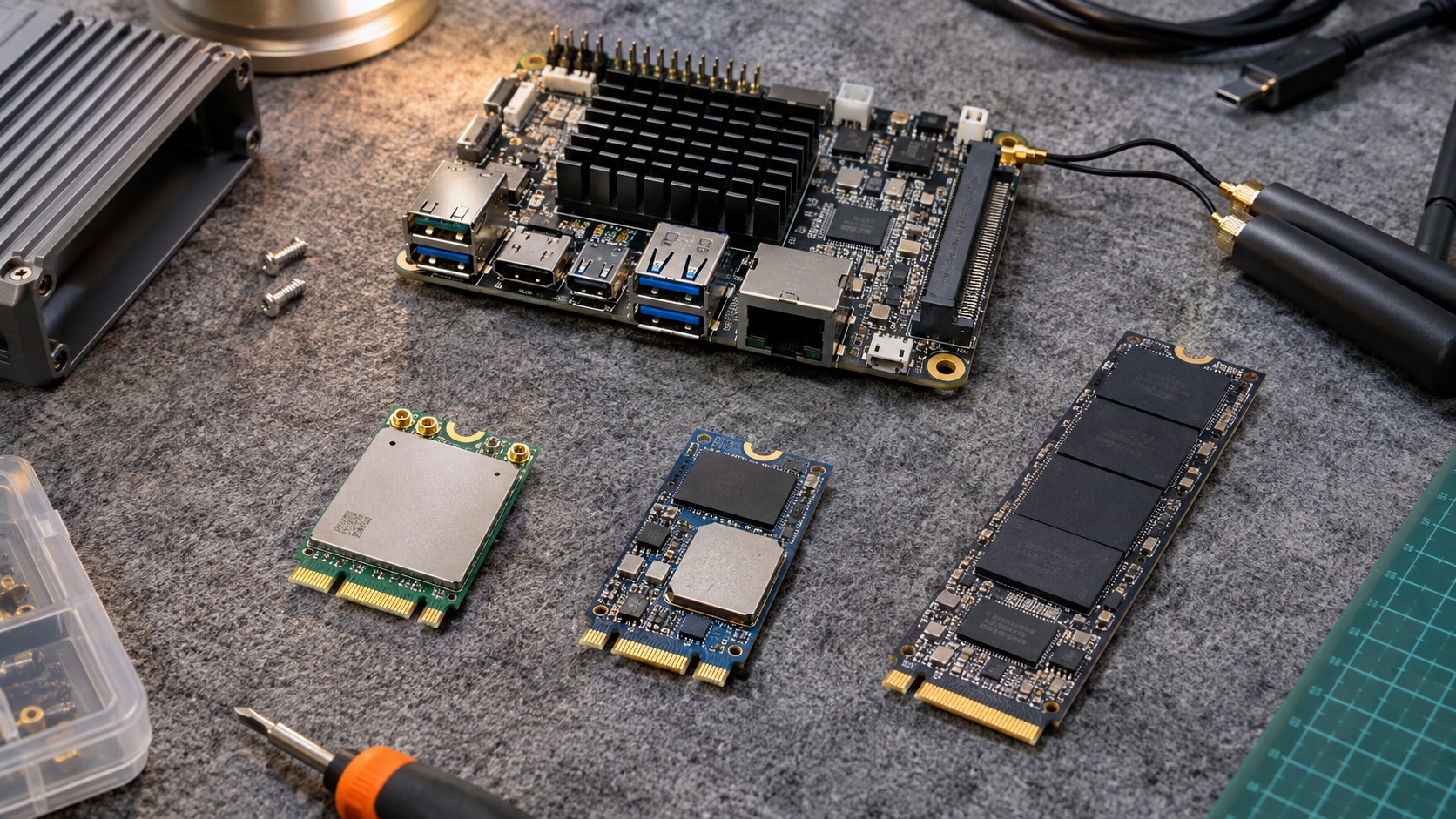
An M.2 module can fit a socket and still be electrically incompatible. The key notch constrains mating, but it does not prove that the board routes the required bus, supplies enough current, or includes the Android driver.
Treat M.2 as a form factor and connector family. Match the exact module to the board schematic, firmware, power design, mechanical envelope, and software support.
Start with the exact module function
Identify whether the module is storage, Wi-Fi, cellular, an accelerator, or another peripheral. Then obtain its interface and power requirements.
Key E is commonly associated with wireless modules, Key M with PCIe storage, and Key B with cellular or other expansion, but actual bus routing varies. Some sockets expose only a subset of possible signals.
A B-key cellular socket may route USB rather than PCIe. An E-key wireless module may require PCIe for Wi-Fi and USB for Bluetooth. Missing one path can produce a partially working module that looks like a software problem.
| Item | What to verify | Why the key is insufficient |
|---|---|---|
| Bus | PCIe, USB, SATA, SDIO, or vendor-specific requirements | Socket may omit needed signals |
| Lanes | Count and generation supported end to end | Mechanical fit does not set bandwidth |
| Power | Voltage, peak current, sequencing | Module load may exceed board budget |
| Control | Reset, enable, wake, disable signals | Platform may leave pins unconnected |
| Mechanics | Width, length, height, standoff | Enclosure clearance can be inadequate |
| Software | Kernel, firmware, Android integration | Enumeration is only the first layer |
Read both schematics and pin descriptions
Request the SBC socket pinout and module integration manual. Mark every required signal as routed, unused by design, or unresolved.
Check voltage domains and pull resistors on control pins. A reset or disable line with the wrong default can hold the module off until software changes it, producing inconsistent cold-boot behavior.
Review reference clock, clock-request, reset timing, and wake support for PCIe modules. For USB modules, confirm the routed speed and signal quality.
Do not use a passive adapter as evidence of compatibility. An adapter can change the connector without adding a missing protocol or power capability.
Check power transients
Wireless and cellular modules can draw short bursts that exceed their average load. Storage and accelerators can also create significant startup or sustained demand.
Measure the module rail at the socket with adequate bandwidth. Include cable-fed input supply limits and voltage drop across protection or switching components.
Verify the board’s current limit and thermal capability. A regulator may support a peak current electrically but overheat inside a sealed enclosure.
The Android SBC power guide provides the system budget. Add each module’s actual operating modes and the possibility of simultaneous display, radio, and storage load.
Confirm mechanical fit beyond length
Common module dimensions encode width and length, but component height and underside population also matter. Check adjacent connectors, heatsinks, shielding, antenna plugs, and enclosure bosses.
Use the correct standoff and screw. Bending a module to reach an incorrect standoff can stress the connector and PCB. Specify torque and service access.
Provide a thermal path where the module requires one. A pad must contact the intended surface with controlled compression and must not bend the module.
For wireless modules, route antenna cables without sharp bends or connector side load. Keep them away from hot surfaces and high-noise cables.
Bring up the electrical link before Android features
First confirm power, reset release, clocking, and bus enumeration. Capture kernel logs and device identifiers. A device missing from the bus should not be debugged at the application API layer.
Next load the correct driver and firmware, check errors, and exercise a basic data path. Only then validate Android framework integration and product behavior.
For a wireless module, test Wi-Fi and Bluetooth independently and simultaneously. For a modem, test data, SIM handling, reconnects, and the intended Android integration. For storage, verify boot support separately from runtime access.
| Bring-up layer | Pass evidence | Common false conclusion |
|---|---|---|
| Power and controls | Stable rail and valid sequence | LED means all power requirements are met |
| Bus enumeration | Correct device identity | Enumeration proves functionality |
| Driver and firmware | Successful load and clean basic operation | Generic driver is production-ready |
| Android integration | Intended API and permissions work | Linux support guarantees Android support |
| Product workload | Sustained performance and recovery | Short benchmark proves field reliability |
Evaluate boot and recovery dependencies
If the module holds the operating system or critical application data, it becomes part of the boot chain. Confirm bootloader support, partition layout, verified boot requirements, and recovery procedures.
A removable storage module can simplify replacement but may complicate identity and data security. Decide which information belongs to the main board and which belongs to the module.
Test absent, loose, failed, and replaced modules. The device should fail into a defined service state rather than repeatedly rebooting without explanation.
The OTA guide is relevant when updates span internal storage and an M.2 device.
Validate suspend, resume, and reset
Power management exposes problems that continuous operation misses. The module may need a specific reset sequence after sleep or may keep the host awake through a wake signal.
Measure idle power with the module installed and compare it with the intended low-power budget. A driver that works functionally can still prevent suspend.
Test repeated sleep cycles, warm reboots, cold boots, and module-specific resets. Record whether the module rail remains on and whether its firmware state survives.
Avoid assuming an SoC reset resets the module. If the board cannot recover a hung device without removing input power, decide whether a controllable module rail is needed.
Control module substitutions
Two modules with the same key and function can differ in current demand, firmware, driver, antenna requirements, temperature range, and lifecycle support.
Qualify replacements with the same matrix as the original. Keep identifiers and firmware versions in the production test record so field differences can be traced.
For cellular or radio products, review the integration and regulatory implications of changing module or antenna. A prior module approval is not a blanket approval for every host configuration.
The component-change guide explains how to connect this review to purchasing.
Ask suppliers for concrete evidence
Request a tested module list with exact part numbers, board revision, BSP version, and known limitations. “Supports M.2” is too broad to support a procurement decision.
Ask for the sustained workload used in validation, recovery behavior after faults, and the maintenance owner for drivers and firmware. A one-time demonstration can leave years of support work with the product team.
Keep at least one approved module from each qualified supplier lot for comparison when field behavior changes.
Frequently asked questions
Are all Key M modules compatible with a Key M socket?
No. Bus routing, power, lane support, dimensions, firmware, and software still need checking.
Can a Wi-Fi module work while Bluetooth does not?
Yes. Some modules use separate buses for the two functions. A socket may route one and omit the other, or the BSP may support only one driver path.
Does Android support any NVMe drive that Linux detects?
Detection is only part of the requirement. Boot, power management, permissions, storage configuration, thermal behavior, and recovery must match the product design.
Release checklist
Retain the socket pin map, approved module part, firmware, driver, power captures, thermal results, and recovery tests. M.2 expansion is dependable when the complete module-host combination is qualified and controlled.