
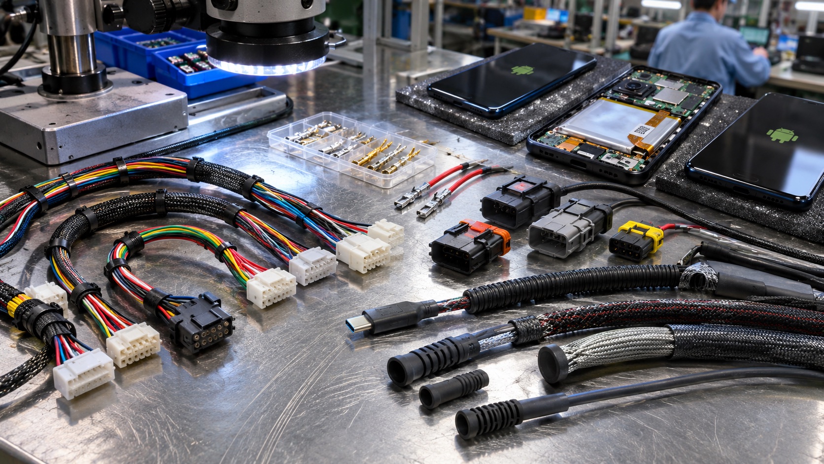
A connector that works on the bench can become the highest-return item in a production device. The failure may come from a half-seated latch, cable tension, fretting under vibration, or a supplier crimp that passes continuity but heats under load.
Choose connectors as a mechanical, electrical, and manufacturing system. The mating pair, terminals, wire, crimp tooling, retention, routing, and inspection standard belong to one controlled assembly.
Start from the installation
Define who connects the cable, how often it is mated, whether access is blind, and what forces reach it. A factory-only internal display cable has different requirements from a field-replaceable power connector.
List temperature, moisture, vibration, cleaning chemicals, dust, and accidental pulling. Include the product’s shipping condition; a loose harness can damage a connector before the device is installed.
Choose keying and color conventions that reduce assembly errors, but do not rely on color alone. Two connectors that can be swapped should either be electrically safe when swapped or mechanically prevented from doing so.
| Requirement | Selection question | Evidence |
|---|---|---|
| Current | Can contacts carry load at actual temperature? | Derating and thermal test |
| Signal speed | Does the complete channel meet requirements? | Cable and connector validation |
| Mating life | How many service cycles occur? | Rated and tested cycle count |
| Retention | Can vibration or cable force unseat it? | Pull and vibration tests |
| Environment | Is sealing required when mated or unmated? | Assembly-specific qualification |
| Assembly | Can operators seat and inspect it consistently? | Pilot build observation |
Use current ratings with context
Connector current ratings depend on contact size, wire gauge, temperature rise, ambient conditions, and how many adjacent contacts are loaded. A headline per-contact rating may not apply to every pin carrying current inside a hot enclosure.
Measure voltage drop across the complete path, including terminals, cable, PCB pads, and protection devices. A small resistance can cause both rail loss and localized heating.
Include startup current and peripheral peaks. USB devices, radios, backlights, and capacitive loads can exceed the average power calculation.
The power-budgeting guide provides the load inventory. Use that inventory to assign connector and wire requirements rather than selecting the harness from steady-state current alone.
Treat high-speed cables as controlled channels
USB, eDP, MIPI, Ethernet, and PCIe links have different channel requirements. Cable length, pair construction, shielding, connector discontinuities, and bend geometry all affect performance.
A cable that has the right pin count is not necessarily suitable. Specify impedance, pair assignment, shield termination, maximum length, routing constraints, and approved construction.
Test the longest and shortest supported assemblies. A very short cable can still fail if the connector pinout or shielding is wrong; a long cable can expose marginal signal quality.
For eDP and internal displays, use the display integration guide to coordinate cable, power, and link training tests.
Design strain relief before the harness drawing
Cable force should be carried by a clamp, enclosure feature, or approved strain-relief method instead of a solder joint or tiny board connector.
Provide a service loop only where it has a defined route. Excess cable can enter a fan, cover an antenna, press against a hot component, or be pinched under the lid.
Specify minimum bend radius and avoid sharp folds at connector exits. Flat cables and micro-coax assemblies can be damaged internally while looking normal from outside.
Photograph the approved routing and include it in work instructions. “Route neatly” is not a reproducible manufacturing requirement.
Control crimp quality
Crimped contacts require the correct terminal, wire, strip length, tooling, and setup. A hand pull is useful but insufficient to qualify the process.
Use supplier-defined crimp height and width limits, pull-force requirements, and cross-section inspection where appropriate. Verify conductor capture, insulation support, strand damage, and terminal position.
Track tooling wear and setup changes. A process can drift after thousands of crimps while the first sample remains excellent.
| Defect | Why continuity may pass | Better detection |
|---|---|---|
| Partial conductor capture | A few strands still conduct | Cross-section and pull test |
| Poor insulation support | Electrical contact remains intact | Flex and strain inspection |
| Terminal not locked | Contact touches during test | Retention and seating check |
| Damaged strands | Low-current test sees little change | Mechanical and loaded thermal test |
| Wrong wire gauge | Initial connection appears normal | BOM and crimp dimensional check |
Do not permit a supplier to substitute wire insulation or terminal plating without review. Both can change temperature, abrasion, corrosion, and processing behavior.
Make assembly mistakes visible
A latch should provide a clear seating indication and remain inspectable. If it disappears beneath a bracket, add a process step that verifies it before the bracket is installed.
Avoid connectors that can be inserted one position off or reversed without obvious resistance. If the design cannot prevent the error, protect the circuit and create an effective test.
Assign harness identifiers and revision markings that remain readable after installation. A serial number on the finished product is not enough to identify a cable-lot issue.
Poka-yoke features are valuable only when they work with real operator access. Watch the pilot build rather than judging the assembly from CAD.
Test dynamic faults
Static continuity misses intermittent contact. Run the product while applying relevant cable motion, vibration, temperature cycling, and connector loading.
Monitor both electrical errors and application outcomes. A brief serial interruption may be harmless if retried, while a short power interruption can reboot the entire system.
Use event logging with enough timing resolution to correlate a fault with the mechanical stimulus. Avoid repeatedly reseating a failed cable before collecting evidence.
Include mating-cycle tests for service connectors and inspect wear, latch damage, plating condition, and contact resistance afterward.
Plan field service and spare parts
A technician should be able to replace the harness without improvising adapters or cutting ties that cannot be restored. Provide access, replacement instructions, routing photos, and approved spare assemblies.
Do not make a low-cost cable field-replaceable if replacement risks damaging a fragile board connector. Sometimes the safer service unit is a larger assembly.
Document torque for threaded connectors and any required sealing parts. Reusing a damaged gasket can turn an electrical repair into a moisture failure.
Tie harness changes into the PCN and substitution process. Cable assemblies deserve the same revision discipline as boards.
Frequently asked questions
Can a connector be selected from its current rating alone?
No. Temperature, adjacent loaded contacts, wire, retention, environment, and mating life all matter. Validate the complete assembly at actual load.
Is a continuity test enough for production harnesses?
It catches opens and miswiring, but may miss poor crimps, weak retention, intermittent contact, and high resistance under load.
Should internal connectors always be glued?
No. Adhesive can hide incomplete seating and complicate service. Use a connector and strain-relief design suited to the forces, then add adhesive only as a controlled process if justified.
Manufacturing handoff
Release the mating parts, terminal and wire specifications, pinout, cable drawing, crimp limits, routing, test procedure, and approved suppliers together. Keep a golden harness with the product baseline. A reliable interconnect is the result of a repeatable assembly, not a familiar connector shape.