
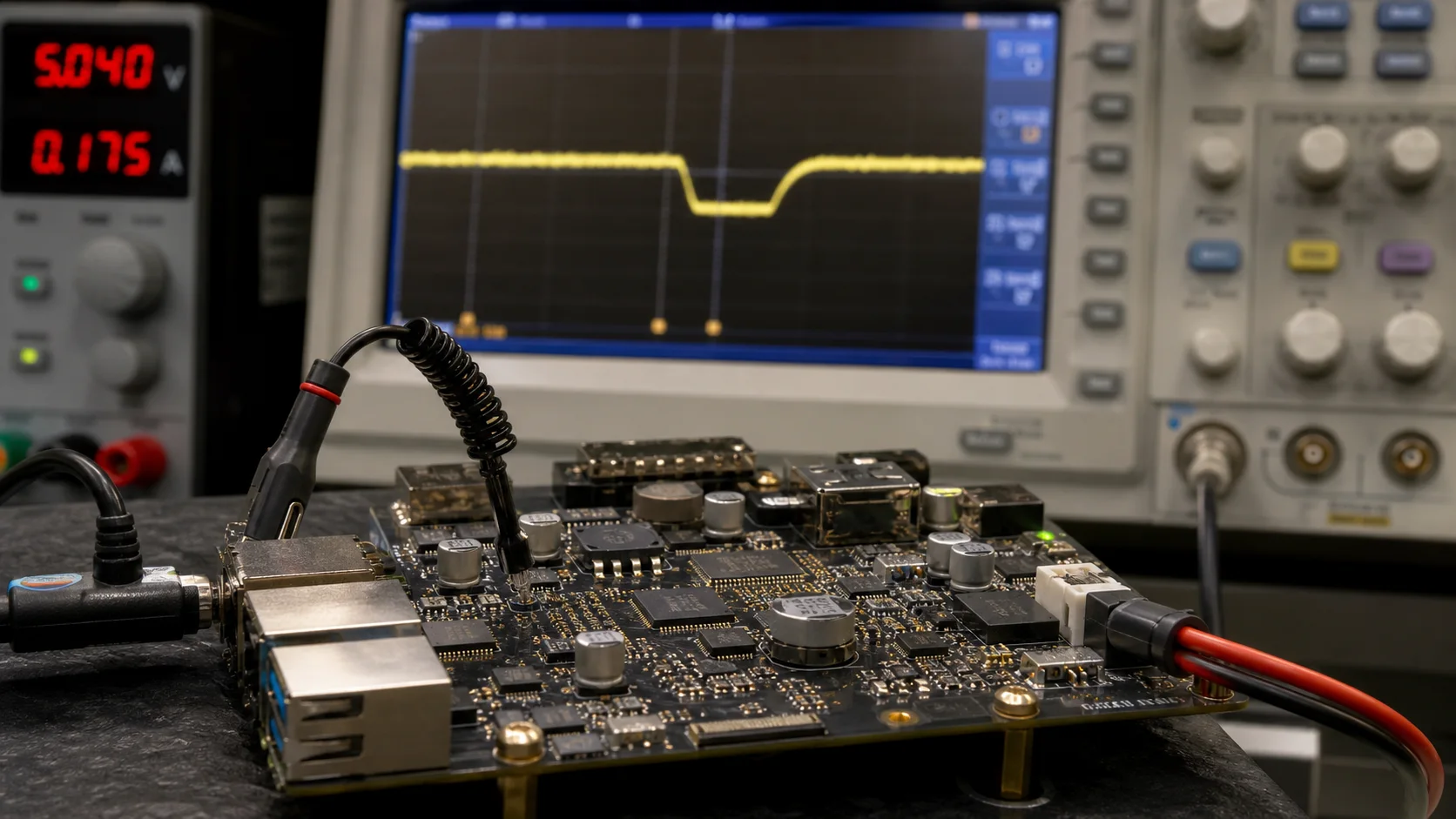
Brownout failures rarely look electrical. They look like a USB camera bug, eMMC corruption, a frozen boot logo, or a unit that restarts only with a bright display. An 800-microsecond rail dip may leave no software timestamp.
The adapter rating is not enough. Include the cable, connector, protection, converters, capacitance, PMIC, board copper, and load steps. Give that path measured margin and define what happens when the margin is gone.
Measure the rail where the board receives it
An adapter marked 12 V, 3 A may meet its label at the adapter output while the SBC sees a much lower voltage during a transient. Cable resistance alone creates a drop of V = I × R; connector resistance, protection FETs, fuses, and PCB traces add more. A 0.35 ohm round-trip path drops 0.7 V at 2 A.
Measure at the board input and at critical downstream rails. Use a short ground spring on the oscilloscope probe, not a long clip that invents ringing. Capture cold boot, maximum backlight, Wi-Fi transmit, CPU/GPU load, camera start, eMMC write, and simultaneous USB insertion. Set the trigger below the normal rail so rare dips are retained.
The site’s power-budgeting guide helps estimate steady and peak demand. Brownout testing adds time: how far does voltage fall, for how long, and how does the PMIC or processor respond?
| Event | Typical electrical concern | What to capture |
|---|---|---|
| Cold boot | Converter soft-start and several rails rising together | Input minimum, rail sequence, reset release |
| Backlight to 100% | Large step at LED driver input | Dip amplitude and recovery time |
| USB peripheral insertion | Inrush plus cable drop | VBUS and main input rail |
| Wi-Fi/cellular transmit | Short repeated current bursts | Minimum voltage over a long capture |
| eMMC write | Load step during data at risk | Core rail, reset, storage activity |
| Sudden unplug | Collapsing input and partial rail sequencing | Power-fail warning and shutdown time |
Average current from a bench meter will miss most of this. Use the meter for energy and the oscilloscope for events.
Build a voltage budget, not a hope budget
Work backward from the board’s minimum input. Subtract adapter tolerance, end-of-life cable and connector drops, protection, converter ripple, and transient response. The remainder is margin.
If the board accepts 9–24 V, do not assume every point in that range behaves equally. A 12 V design can fall below an upstream converter’s undervoltage lockout during a long cable transient. A 24 V input may improve cable-drop margin but increase dissipation in protection and conversion stages. Test the intended nominal voltage with the intended cable length.
For 5 V boards, margin is tighter. USB-style cables vary widely, and a connector that feels mechanically fine can add enough resistance to cause resets under load. Lock the cable specification for production. “Any 5 V adapter” is not a power requirement.
Decide between ride-through and controlled reset
The design needs two behaviors:
- Ride through short, expected transients without disturbing Android.
- Reset or shut down cleanly when the input is no longer trustworthy.
Bulk capacitance can bridge a short event. A first estimate is C = I × Δt / ΔV. Holding 2 A for 10 ms with a 0.5 V drop suggests 40,000 µF before ESR, temperature, aging, and load variation. A capacitor cannot fix every source problem.
Use capacitance near the load for high-frequency response, a converter with suitable transient performance, and upstream energy storage only where calculations and tests justify it. Large input capacitors also create inrush and can upset hot-plug controllers or PoE negotiation.
When the input stays low, a defined reset is safer than marginal operation. A voltage supervisor monitors a rail and holds reset active until voltage is safely above a threshold for a specified delay. TI’s discussion of power-fail comparators and watchdog supervisors illustrates the useful distinction: an early power-fail warning can arrive before the hard reset threshold.
That warning window can let a microcontroller isolate outputs or signal Android. It is usually too short for Android to close every application gracefully unless the product includes deliberate hold-up energy.
Protect storage by controlling writes
Modern filesystems and eMMC tolerate power loss better than old SD-card designs, but data may still sit in an application buffer, journal, block layer, device cache, or flash translation layer.
Separate data by importance. Configuration that changes once should not be rewritten every few seconds. Telemetry can use an append pattern and tolerate loss of the last record. Credentials and device identity need atomic replacement, backup, and validation. Databases should use transactions and a corruption recovery policy that has been tested with the actual storage device.
With power-fail warning and hold-up, stop new work, flush essential state, then signal readiness to cut power. A returned sync does not prove every internal flash operation is complete. Test a nearly full device.
Include the display and peripherals
The board is only part of the load. A display backlight may consume more power than the SBC. USB scanners, cameras, printers, LTE modems, and relays add inrush or pulsed demand. Powering them from a separate regulator can reduce coupling, but only if grounds, sequencing, and fault behavior are still controlled.
A useful test runs the real application while changing all high-load states at once: maximum backlight, video playback, Wi-Fi upload, USB camera stream, and storage write. It is not a realistic user action. That is the point. Validation should find the electrical edge before the field does.
For PoE products, pair this test with PoE power design and verify startup classification, splitter output, cable length, and load transients together.
Use a repeatable brownout test matrix
Use a fixture for controlled ramps, dips, repeated interruptions, and hard disconnects. A programmable supply handles slow events; a MOSFET switch and pulse generator make fast cuts repeatable. Record waveform and result under one test ID.
| Test | Variation | Pass condition |
|---|---|---|
| Input ramp | Slow and fast rise at min/nominal/max input | One clean boot; reset not chattering |
| Short dip | Sweep depth and duration | Ride-through or one controlled reset |
| Repeated dip | 100–1,000 cycles near threshold | No boot loop or storage damage |
| Power cut during write | Random cut while database and eMMC are active | Defined data-loss window; clean recovery |
| Cable/connector aging | Add worst-case series resistance | Rail remains within budget |
| Peripheral inrush | Hot-plug each supported USB/load option | No reset; port protection behaves correctly |
| Auto-recovery | Restore power after every failure mode | Product returns to managed application state |
Run the matrix at temperature extremes. Capacitor ESR, battery performance, converter limits, and cable resistance move with temperature. And repeat it on multiple board and storage lots. One golden sample can hide the exact marginal condition you need to expose.
Make resets diagnosable
If the PMIC or supervisor exposes reset cause, capture it early in boot and persist a compact event record. Add input-voltage telemetry if the hardware provides a trustworthy ADC path. Distinguish watchdog, software reboot, thermal shutdown, and undervoltage.
Do not write a large log on every brownout; that creates another risky write. A small counter with checksummed or redundant storage is often enough. Fleet data showing one hardware revision accumulating undervoltage resets is much more useful than a support note saying “random reboot.”
Frequently asked questions
Can software fix an Android SBC brownout?
Software can reduce load, respond to an early warning, and recover data. It cannot operate a processor below its valid rail or remove cable resistance. Fix the electrical path first.
Is a larger capacitor always better?
No. More capacitance may improve hold-up but increases inrush, board space, cost, and stress on connectors or hot-plug circuits. Size it from a measured load, permitted voltage drop, required time, ESR, tolerance, temperature, and aging.
Should an Android product automatically reboot when power returns?
Usually yes for unattended equipment, but verify outputs start in a safe state and the application recovers without human login. Document exceptions for battery products and regulated equipment.
What good looks like
A robust product has a boring power signature. Load steps create bounded dips. Short disturbances are ignored. Long disturbances produce one clean reset or controlled shutdown. Power restoration leads to a known boot path, and the event is visible in diagnostics.
The key is to stop treating brownout as an adapter-sizing exercise. It is a system behavior involving copper, converters, reset thresholds, storage, Android boot, and the peripherals customers actually connect. Put all of them on the bench at the same time.
Primary references
- Texas Instruments: Using power-fail comparators and watchdog supervisors
- Texas Instruments: Reset and power-supply supervisor application note